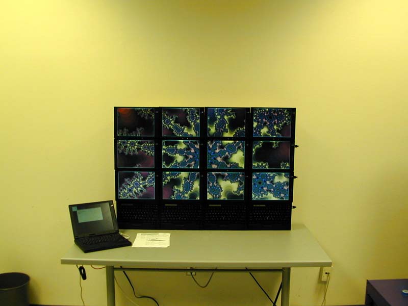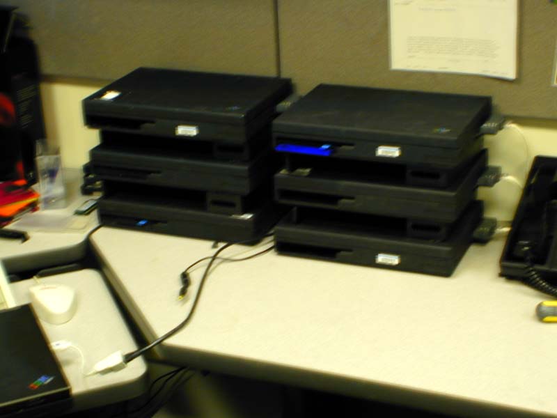
Setup of the IBM Thinkpad 760E's as cpu servers required some changes to the pccpcdisk file in order to add support for graphics and pcmcia. Our cpurc . is also modified to include sections from termrc inorder to run rio on the cpu server.
These nodes have a non standard disk layout to support a 1.4G root filesystem(kfs) as well as a 500Mb cache filesystem(cfs) and nvram, the partition layout is:
 disk/prep /dev/sdC0/plan9
  9fat                  0 20482      (20482 sectors, 10.00 MB)
  fs                20482 3000000    (2979518 sectors, 1.42 GB)
  cache           3000000 4032880    (1032880 sectors, 504.33 MB)
  nvram           4032880 4032881    (1 sectors, 512 B )
  swap            4032881 4128705    (95824 sectors, 46.78 MB)
The nodes are setup to use a cfs disk cache, the plan9.ini which supports this and booting off of the fileserver by default. old plan9.ini using kernel on local disk:
	bootfile=sdC0!9fat!9pccpud
	bootdisk=local!#S/sdC0/fs
	bootargs=il
	cfs=#S/sdC0/cache
	*nomp=1
	distname=plan9
	partition=new
	ether0=type=EC2T
	monitor=xga
	vgasize=1024x768x8
	mouseport=ps2
new plan9.ini using kernel from fileserver:
	bootdisk=local!#S/sdC0/fs
	bootargs=il
	cfs=#S/sdC0/cache
	*nomp=1
	distname=plan9
	partition=new
	ether0=type=EC2T
	bootfile=ether0
	monitor=xga
	vgasize=1024x768x8
	mouseport=ps2
The bootfile arg tells the machine that it will get it's kernel using bootp/tftp over the network from the auth server. The auth server knows which kernel to send based on the bootf arg in /lib/ndb/local in this case it is /386/9pw
All the powerwall machines are clones of the same basic setup to make a clone we insert a extra hard drive into the 760 floppy/cdrom bay using an adapter made for this purpose. boot the machine off its disk by typing "local" at the boot prompt and then dd the drive using:
dd -if /dev/sdC0/data -of /dev/sdC1/data -bs 5000000sync the disks, power down the machine and remove the secondary disk and insert it into the clone.
The initial 6 cpu servers

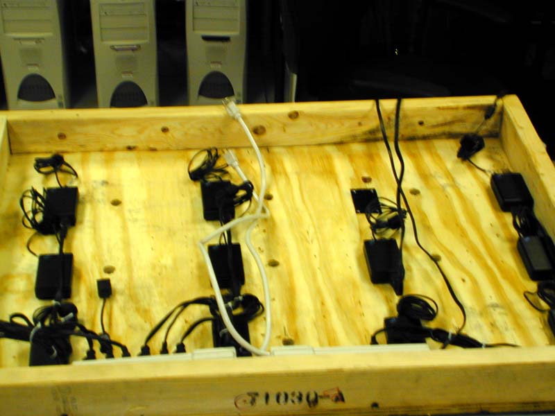
The base from a discarded shipping crate was just the
right side for mounting the powerwall on. We drilled holes
for each power cord and network cord and the used velcro and
rivets to attach the power supplies to the back of the crate.
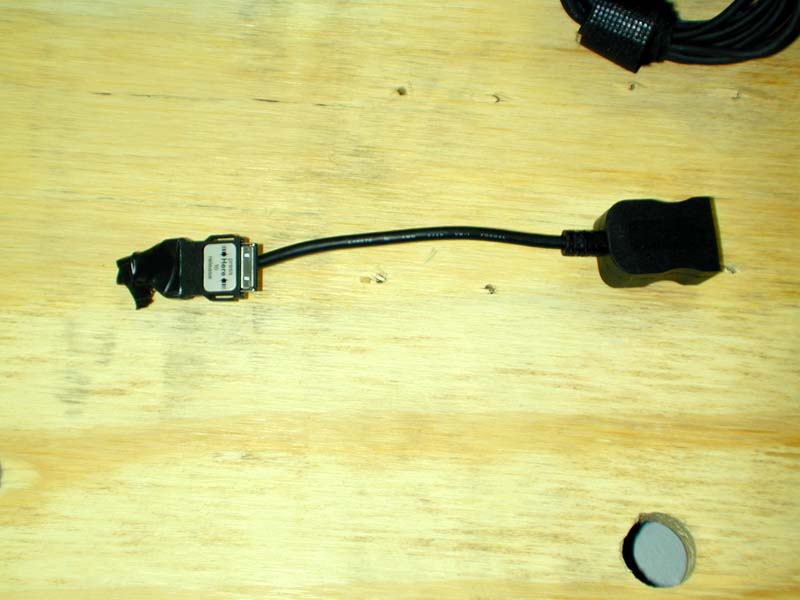
The custom bent network "dongle" that fits into the hole left
by the removal of the thinkpad modem. This allow the machines
to be placed side by side.
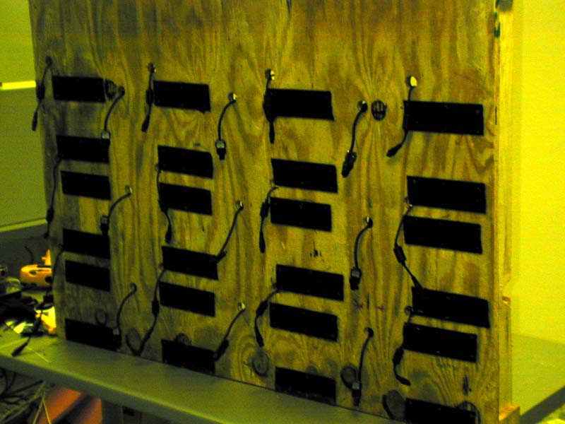
The front of the crate, with the power cords, network dongles
and velcro attachments in place,
following a suggestion by John
"man-beast"
Patchett, each piece of velcro is riveted to the crate.
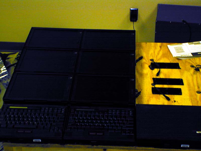
Installing the nodes. Each power cord fits into the hole
left by the cdron/floppy bay, and each network dongle fits
into the modem port. The piece of paper is used under the node
to keep the velcro from sticking until the node is in position.
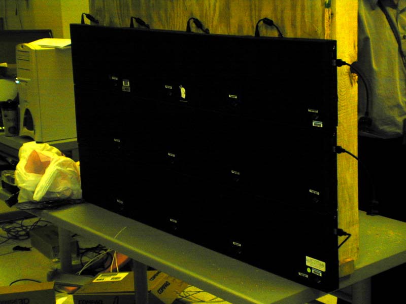
All the nodes mounted on the crate (with screens closed)
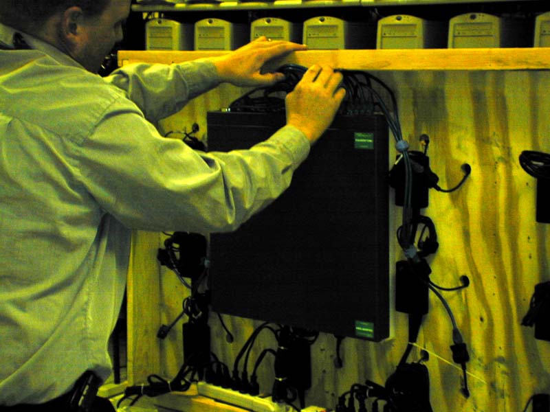
Kip hooking up the network cables.
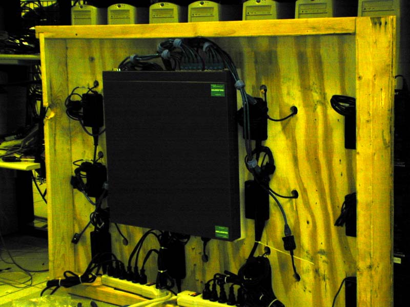
Back of the completed powerwall
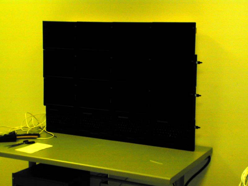
Front of the completed powerwall.
Finally, up and running plan9
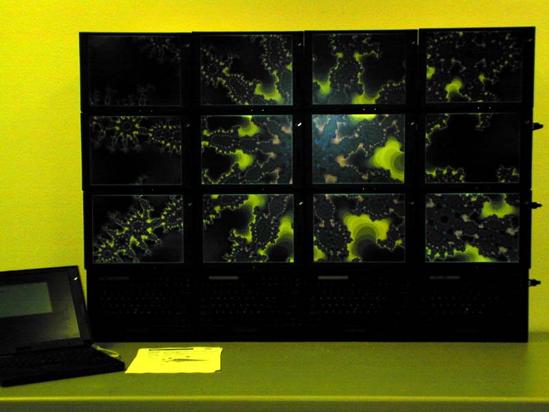
All done.
